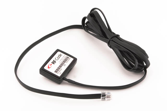
The easy-to-deploy wireless RF Code & Raritan solution enables IT racks to be instrumented quickly for power monitoring and eliminates the time and cost associated with expensive wired Ethernet connections. Deploying the joint solution simply involves installing the Raritan PDU into the rack and then plugging an RF Code sensor tag into a Raritan PDU. All IP address association, configuration, and IP address maintenance is eliminated drastically reducing the cost of PDU power monitoring.
Features:
- Encoded Radio Transmissions at 433 MHz
- Power consumption and utilization trend monitoring, including:
- Main PDU Data
- PDU Phase Data
- PDU Outlet Data
- PDU Breaker Data
- Works with Raritan’s “RF Code Ready” PX family of rack PDUs
- Integrates with RF Code’s Sensor Manager and Asset Manager software solutions
- Easy-to-Deploy, “Wire-free” Monitoring
- Low Power Consumption for Long Battery Life
In Detail
RF Code Wire-Free CDU Sensor Tag Integration for Server Technology
RF Code and Server Technology have worked collaboratively to integrate RF Code’s wire-free sensor technology with the industry leading cabinet power distribution units (CDUs) from Server Technology. The result of this effort is the RF Code R170 CDU Sensor Tag for Server Technology which enables data center managers to monitor real-time power consumption and utilization via RF Code’s wire-free sensor network and Sensor Manager application. The RF Code R170 CDU Sensor Tag works in concert with the “RF Code Ready” CDU’s from Server Technology. The compatible products from Server Technology include CDU’s with Per Inlet Power Sensing (PIPSTM) with or without Per Outlet Power Sensing (POPSTM) functionality.
The easy-to-deploy wireless RF Code & Server Technology solution enables IT racks to be instrumented quickly for power monitoring and eliminates the time and cost associated with expensive wired Ethernet connections. Deploying the joint solution simply involves installing the Server Technology CDU into the rack and then plugging an RF Code sensor tag into the CDU. All IP address association, configuration, and IP address maintenance is eliminated drastically reducing the cost of CDU power monitoring. The R170 CDU Sensor Tag simply plugs into the serial port on the Server Technology CDU via a locking RJ45 connector. When connected, the R170 CDU Sensor Tag collects vital power usage statistics and transmits the information using RF Code’s patented radio frequency technology to an RF Code Reader which is connected to the Ethernet network. The RF Code Readers decode all of the RF transmitted data which is then collected by RF Code’s applications (Zone Manager, Sensor Manager, and Asset Manager).
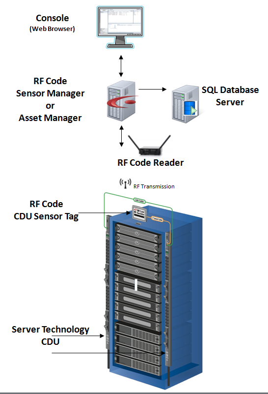
The CDU Sensor Tag data collection and reporting cycle involves sets of data at two levels of timeliness. The most critical power information is reported every 10 minutes and while information that is less time critical is reported every hour. These cycles result in the following reporting periods:
- Per-Phase voltage/power-factor/watt-hours transmitted every 10 minutes
- Per-breaker amperage transmitted every hour
- Per-socket watt-hours and configuration transmitted every hour
- Per-socket power-factor transmitted every hour
- Feed Line ID, amperage and overload status every hour
- CDU model and CDU serial number packets transmitted at least once per hour
- Per -breaker tripped status is sent in real-time upon a state change
- Individual outlet state change (on/off) is sent in real-time for switched CDU’s
The CDU Sensor Tag for Server Technology provides the following power attributes which are surfaced in the RF Code Zone Manager middleware as well as the Sensor Manager and Asset Manager applications:
- Main CDU Data:
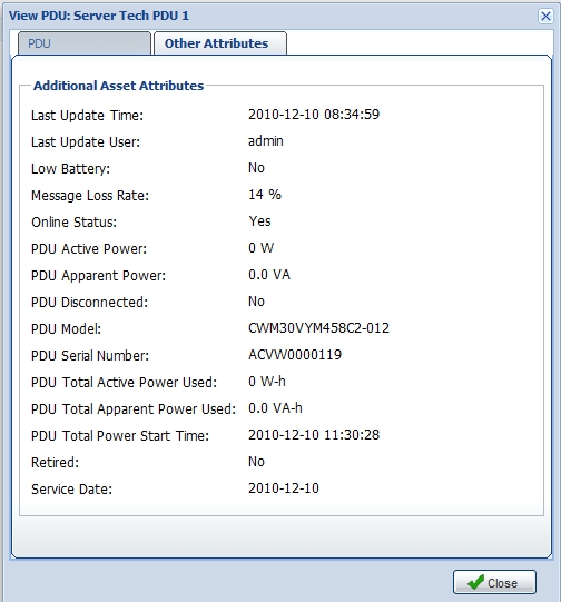
- CDU Model
- CDU Disconnected
- CDU Serial Number
- CDU Active Power
- CDU Apparent Power
- CDU Total Active Power Used
- CDU Total Apparent Power Used
- CDU Total Power Start Time
- CDU Phase Data:
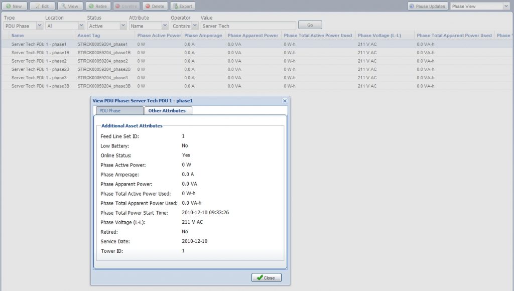
- Phase Active Power
- Phase Amperage
- Phase Apparent Power
- Phase Power Factor
- Phase Total Active Power Used
- Phase Total Apparent Power Used
- Phase Total Power Start Time
- Phase Voltage (L-L)
- Phase Voltage (L-N)
- CDU Outlet Data:
- Outlet Active Power
- Outlet Amperage
- Outlet Apparent Power
- Outlet Total Active Power Used
- Outlet Total Apparent Power Used
- Outlet Total Power Start Time
- Outlet Voltage
- CDU Feed Line Data:
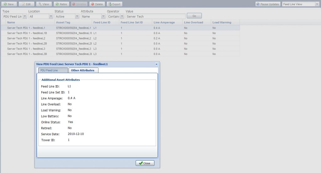
- Feed Line ID
- Line Amperage
- Line Overload
- Line Warning
- CDU Breaker Data:
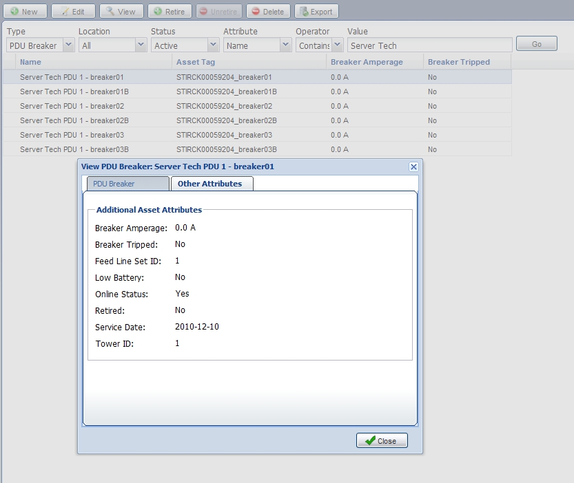
- Breaker Amperage
- Breaker Tripped
By utilizing the power calculated attribute feature of RF Code’s Asset Manager and Sensor Manager applications, Active Power and Apparent Power metrics can be produced for the various locations defined such as the rack, the row, and the entire data center. Furthermore all of the power information described above is available for use by Asset Manager and Sensor Manager’s data management features such as:
- Live table views
- Map views
- Interactive graphing
- Scheduled reporting and graphing
- Alerting and thresholds
The following illustrations show the information collected by the RF Code CDU Sensor Tag for Server Technology being utilized by Sensor Manager and Asset Manager in a variety of different ways:

